Problem Statement
Flooding is a serious problem in many urban and semi-urban areas, especially during heavy rainfall. Poor drainage infrastructure, blocked drainage systems, and the absence of real-time monitoring often cause water to accumulate on roads, residential areas, and public facilities. This leads to damage to property, disruption of transportation, environmental pollution, and risks to human safety.
In many places, drainage systems are still operated manually and lack an efficient monitoring mechanism. Authorities usually become aware of flooding only after it has already caused significant damage. The delay in detecting rising water levels and responding to them makes flood management ineffective. Additionally, the absence of automated control systems means that pumps or drainage gates cannot be activated immediately when water levels reach critical points.
Therefore, there is a need for a smart and automated system that can continuously monitor water levels in drainage channels or flood-prone areas and respond quickly when a potential flood is detected. By integrating sensors, microcontrollers, and automated drainage mechanisms, it is possible to detect rising water levels in real time and automatically activate pumps or drainage gates to remove excess water.
The Smart Flood Detection and Automatic Drainage Control System aims to address this problem by developing a system that monitors water levels using sensors, processes the data through a microcontroller, and automatically controls drainage mechanisms to reduce the risk of flooding. This system can help improve flood management, reduce damage caused by floods, and provide an efficient and reliable solution for urban water control.
Objectives
1. General Objective:
The main objective of this project is to design and develop a smart system that detects rising
water levels and automatically controls drainage mechanisms to prevent flooding in vulnerable areas.
2. Specific Objectives:
a. To design a water level monitoring system
Develop a system that continuously measures water levels in drainage channels using appropriate sensors.
b. To develop an automated flood detection mechanism
Program a microcontroller to analyze sensor data and detect when water levels exceed a predefined safety threshold.
c. To implement an automatic drainage control system
Activate pumps or open drainage gates automatically when high water levels are detected to remove excess water.
d. To provide real-time alerts and monitoring
Send notifications or display water level status through indicators, alarms, or a digital monitoring interface.
e. To build and test a working prototype
Construct a functional prototype to demonstrate the system’s ability to detect floods and automatically control drainage.
System Architecture
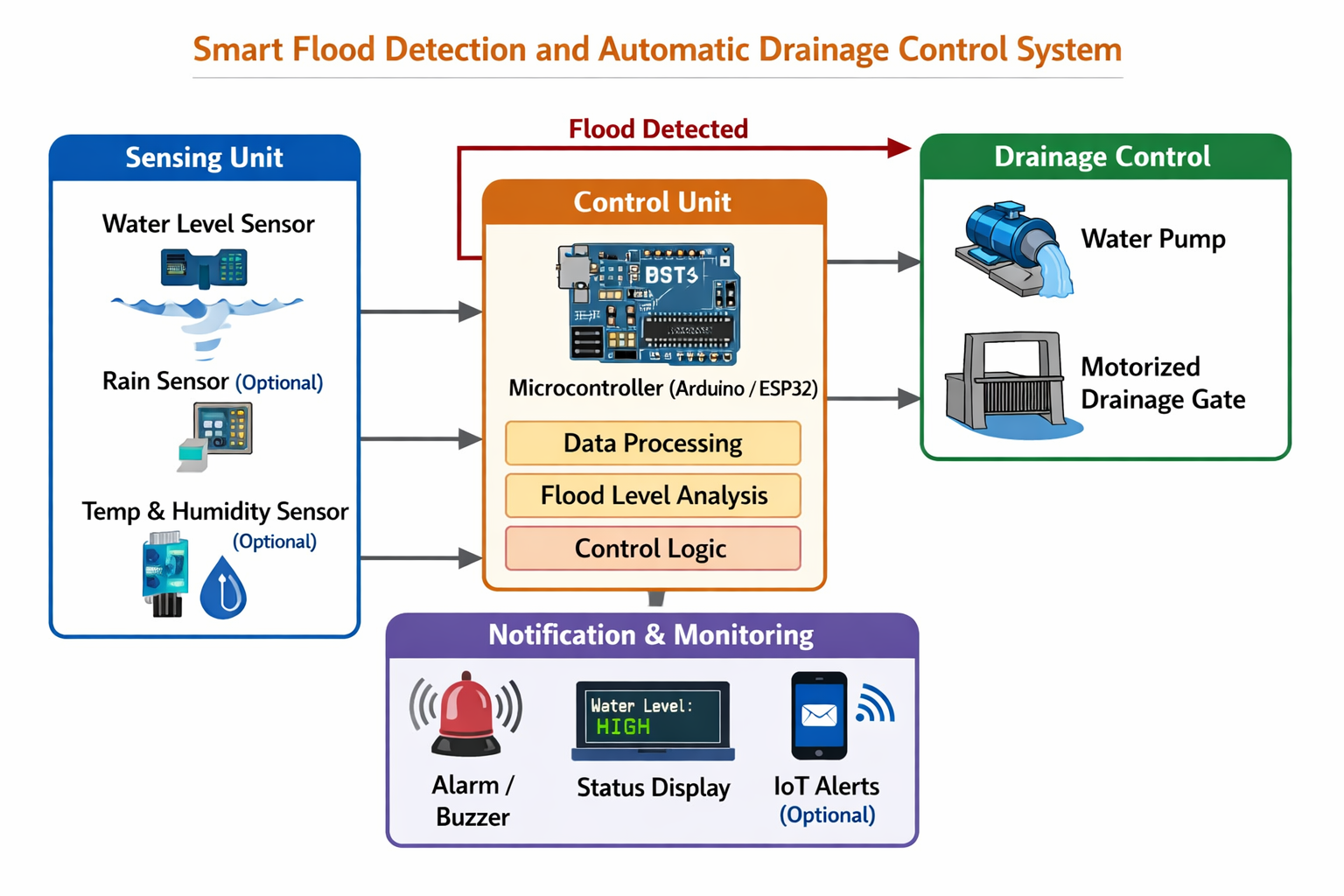
The Smart Flood Detection and Automatic Drainage Control System is designed to monitor water levels in drainage channels or flood-prone areas and automatically control drainage mechanisms to prevent flooding. The system integrates sensors, a processing unit (microcontroller), a control mechanism, and an alert system to ensure fast and efficient flood management.
1. System Working Principle
The system operates by continuously measuring the water level using sensors installed in a
drainage channel, river, or water collection area. These sensors send real-time data to a
microcontroller, which processes the information and determines whether the water
level is safe or approaching a flood condition.
When the water level exceeds a predefined threshold:
- The microcontroller automatically activates a water pump or opens a drainage gate to remove excess water.
- At the same time, the system can trigger alerts such as alarms, LED indicators, or digital notifications to inform users or authorities.
2. Main Components of the System Architecture
a. Sensing Layer (Input Layer)
This layer is responsible for collecting environmental data.
Possible sensors include:
- Water Level Sensor or Ultrasonic Sensor:- measures water level in the drainage system
- Rain Sensor (optional):- detects rainfall intensity
- Temperature/Humidity Sensor (optional):- monitors environmental conditions
b. Processing Layer (Control Unit)
This is the brain of the system.
A microcontroller (such as Arduino, ESP32, or Raspberry Pi) receives sensor data and performs the following tasks:
- Analyzes water level readings
- Compares values with predefined thresholds
- Determines whether flooding conditions exist
- Sends commands to activate drainage mechanisms
c. Control Layer (Actuation System)
This layer performs the physical action to prevent flooding.
Key components include:
- Water Pump:- activated to remove excess water when flooding is detected
- Drainage Gate or Valve:- opens to allow water to flow out of the area
- Relay Module:- allows the microcontroller to control high-power devices like pumps
This layer provides real-time system feedback.
Possible features include:
- LED indicators showing water level statu
- Buzzer alarm for flood warning
- LCD display to show sensor data
- IoT monitoring (optional) using WiFi to send alerts to a mobile app or web dashboard
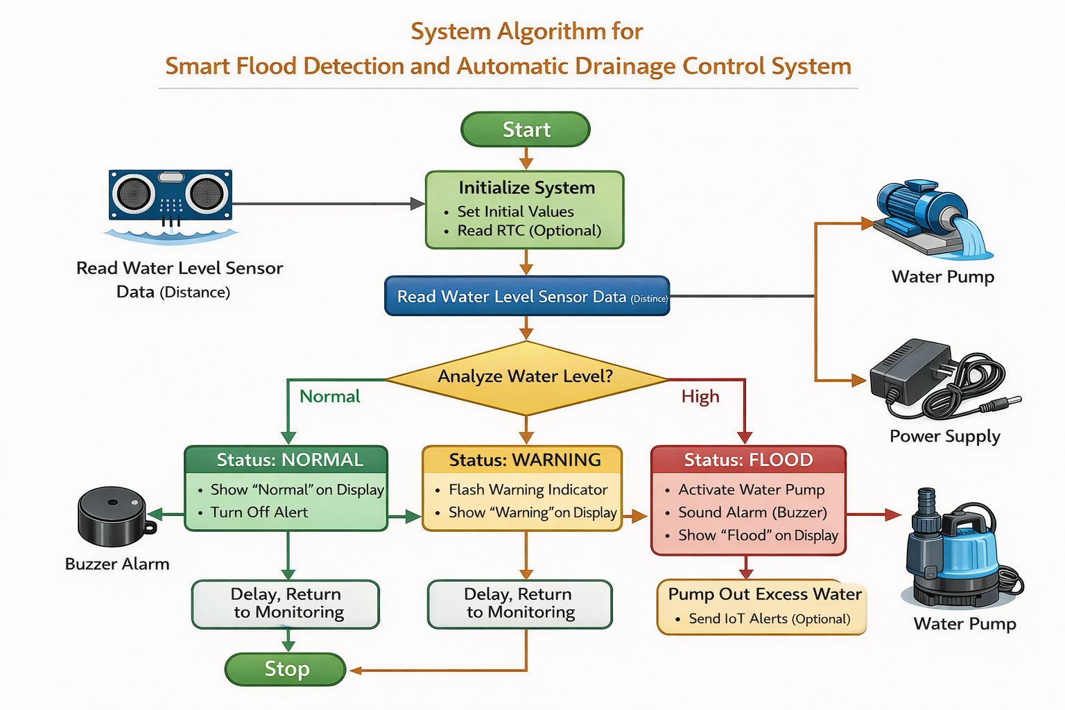
3. Basic System Operation Flow
- Sensors measure water level continuously.
- Sensor data is sent to the microcontroller.
- The microcontroller analyzes the water level.
- If water level is normal, the system remains in monitoring mode.
- If water level is high, the system activates the pump or drainage gate.
- Alerts are sent to notify users of potential flooding.
- Once water returns to a safe level, the system automatically stops the pump.
Hardware Components
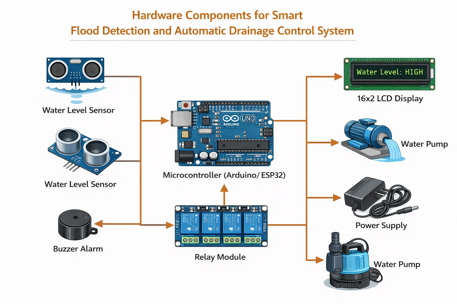
Below are the main hardware components used in this project, including their name, function.
1. Water Level Sensor (Ultrasonic Sensor – HC-SR04)
The water level sensor measures the distance between the sensor and the water surface. From this distance,
the system calculates the water level in the drainage channel.
2. Microcontroller (Arduino Uno / ESP32)
The microcontroller acts as the brain of the system,
processing sensor data and controlling system operations.
3. Water Pump
The water pump removes excess water from the drainage system when flooding is detected.
4. Relay Module
The relay module allows the microcontroller to control high-power devices like the
water pump safely.
5. Power Supply
The power supply provides electrical energy to operate the system components.
6. Buzzer Alarm
The buzzer provides an audible warning when flood conditions are detected.
7. LCD Display (16x2 LCD)
The LCD display shows sensor data and system status.
Software Components
The software requirements specify the tools, platforms, and programming needs necessary to implement the flood detection and automatic drainage control system.
1. Programming Environment
Arduino IDE (for Arduino Uno or ESP32 microcontroller)
Alternative: PlatformIO or ESP-IDF (for ESP32)
Purpose: To write, compile, and upload the microcontroller program that reads sensor data and controls output devices.
2. Programming Language
C / C++ for Arduino-based microcontrollers
Python (optional) for IoT integration if using Raspberry Pi or cloud monitoring
Purpose: To process sensor readings, execute control logic, and manage device operations.
3. Microcontroller Libraries
Ultrasonic sensor library (e.g., NewPing for Arduino)
LCD library (e.g., LiquidCrystal_I2C)
Wi-Fi / IoT libraries (e.g., WiFi.h and HTTPClient.h) if sending remote alerts
Purpose: To simplify hardware interfacing and ensure accurate communication between the microcontroller and sensors/devices.
4. Operating System Requirements
Computer OS for programming microcontroller:
Windows, Linux, or macOS
Purpose: To run Arduino IDE or equivalent programming software.
5. Simulation/Monitoring Tools (Optional)
Serial Monitor (built-in Arduino IDE) for real-time debugging and monitoring of sensor data.
Mobile app or web dashboard if IoT integration is used.
6. Functional Requirements
Continuously read water level data from the sensor.
Compare water level with predefined threshold values.
Activate pump, alarm, and display automatically when water level exceeds limits.
Provide visual feedback (LCD) and audible alerts (buzzer).
(Optional) Send notifications to remote monitoring devices.
7. Non-Functional Requirements
Reliability: System must respond accurately to changing water levels.
Efficiency: Minimal delay between water level detection and device activation.
Scalability: Software should support adding multiple sensors or IoT integration in the future.
User-Friendliness: Display information in an easy-to-understand format.
Prototype Design
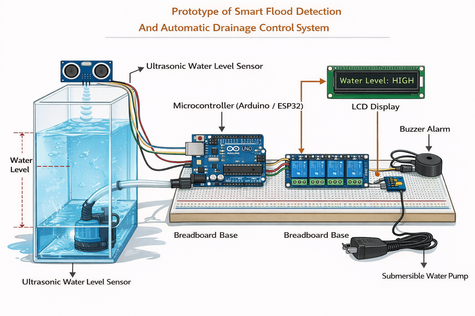
The prototype design represents a small-scale working model of the proposed flood detection and drainage control system. The purpose of the prototype is to demonstrate how the system detects rising water levels and automatically activates a drainage mechanism to prevent flooding.
The prototype consists of a water container that simulates a drainage channel, a water level sensor, a microcontroller unit, a relay module, and a water pump. The sensor measures the water level continuously and sends the data to the microcontroller. When the water level exceeds a predefined threshold, the microcontroller activates the water pump through the relay module to remove excess water.
Prototype Components
- Water container or tank (simulating drainage)
- Ultrasonic water level sensor (HC-SR04)
- Microcontroller (Arduino Uno or ESP32)
- Relay module
- Water pump
- Buzzer alarm
- LCD display
- Power supply
Prototype Working Principle
- Water is gradually added to the tank to simulate rising levels.
- The ultrasonic sensor continuously measures water depth.
-
The microcontroller analyzes sensor data and checks thresholds:
- Normal level: No action, system monitors.
- Warning level: LCD shows warning, buzzer sounds.
- Critical level (Flood): Microcontroller activates pump via relay module.
- Excess water is pumped out automatically until safe water level is restored.
- System returns to monitoring mode.
Circuit Diagram
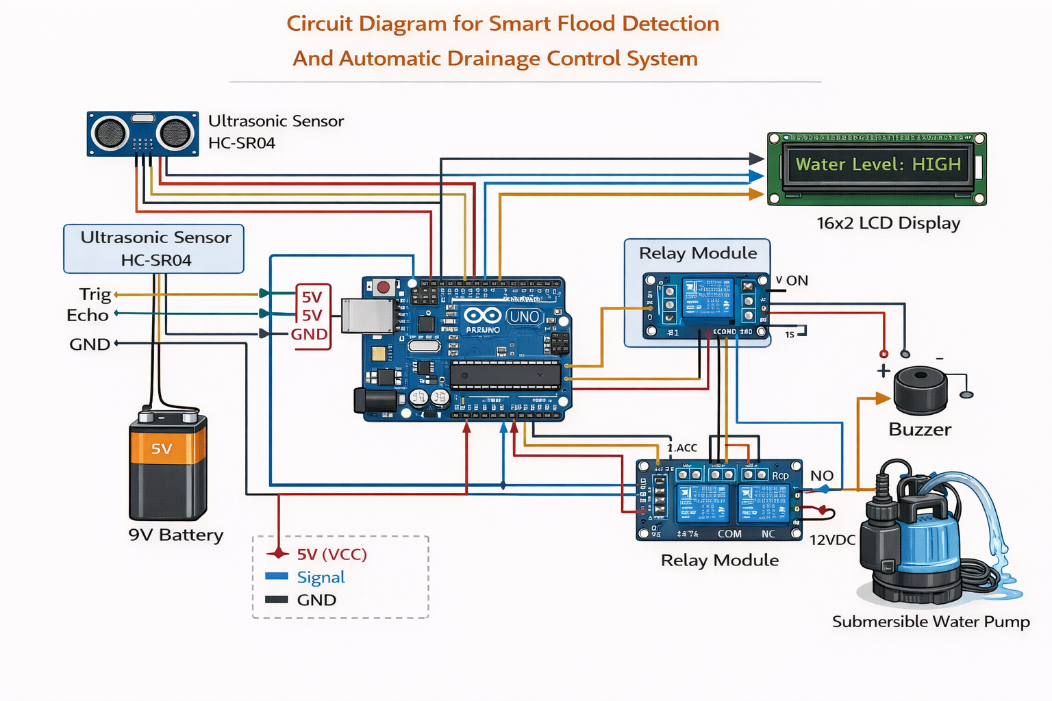
The circuit diagram illustrates how all the hardware components are electrically connected to the microcontroller and how signals flow between sensors, actuators, and output devices.
Circuit Components
- Ultrasonic Water Level Sensor (HC-SR04):- measures water depth.
- Microcontroller (Arduino Uno / ESP32):- processes data and controls devices.
- Relay Module:- switches the water pump ON/OFF.
- Submersible Water Pump:- removes excess water.
- Buzzer Alarm:- alerts for flood conditions.
- 16x2 LCD Display:- shows real-time water levels and system status.
- Power Supply:- provides energy to all components.
Project Timeline
Phase 1: Planning and Requirement Analysis
Identify flood-related problems, define project objectives, conduct literature review, select hardware and software requirements, and design system architecture and block diagram.
Phase 2: Hardware Procurement and Setup
Purchase components such as ultrasonic sensors, microcontroller (Arduino/ESP32), relay module, water pump, LCD, and buzzer. Assemble components and ensure proper power connections for safe operation.
Phase 3: Software Development
Program the microcontroller to read water level data, analyze thresholds, control the pump, display status on LCD, and trigger buzzer alarms. evelop optional IoT dashboard or notifications for remote monitoring.
Phase 4: Integration and Prototype Testing
Combine hardware and software, test the full system under simulated flood conditions, calibrate sensors, verify pump activation, and ensure alerts and display updates function correctly.
Phase 5: Performance Evaluation and Optimization
Measure response time, system reliability, sensor accuracy, and pump efficiency. Optimize thresholds, software logic, and component placement for maximum efficiency and stability.
Phase 6: Documentation and Presentation
Prepare final report, poster, and presentation slides including system diagrams, methodology, prototype photos, test results, and conclusions for submission and Engineering Design Exhibition.
Conclusion
Flooding is a major challenge in urban and semi-urban areas, causing property damage, transportation disruption, and risks to human safety. The Smart Flood Detection and Automatic Drainage Control System provides an effective solution by combining real-time water level monitoring with automated drainage control.
This project demonstrates a multidisciplinary approach, integrating sensors, microcontrollers, actuators, and software to detect rising water levels and automatically activate pumps or drainage gates. The system also provides alerts through a buzzer and displays water status on an LCD, ensuring timely response to potential floods.
The prototype proves that such a system is feasible, reliable, and efficient. It can reduce flood risks, save property, and improve community safety. With further enhancements like IoT monitoring or AI-based prediction, this system can be scaled for real-world applications and smart city infrastructure.
In summary, this project successfully addresses flood management challenges through automation, demonstrates strong multidisciplinary collaboration, and provides a practical, low-cost solution suitable for both educational and real-world deployment.